Look at this picture...:

Graticule indicator was red,
Vertical Display indicator was red,
Power On indicator was green,
Uncal led was yellow and
Screen graticule was lighting.... !...That's ALL and Spectrum analyser stays indefinitely in this poor status.
I have removed the Spectrum Cover and Checked the power supply voltages on "Z axis and RF Interface (A70)" pcb with a multimeter.


All voltages were correct except the -15V which was 0 Volt !.


On Service Manual, we have discovered the -15V power supply schematics (#44).
It receives an unregulated (but filtered) -17V furnished by the inverter transformer output.


All "second side" regulators are linear units and -12V has its output adjusted by the U3036/a (LM358).
The U3036/b Op. Amp was used as a foldback current limiting controller.
The transistors used are 2N2007 TO18 for Q3023 and an old G.E. (or Motorola) D45H11 TO220 case, able to sustain an Collector current of 10 DC Amp.
All power supplies were expecting to be located in the instrument backside.
My first action was to ...take lot of pictures of the instrument before to open it ... and lot of pictures during all states of dismounting process...
...You've heard of the legend of Tom Thumb, which marking his path with small stones to be able to find back his way...

Once you have removed the power supply for the first time... it's a very simple process,
but, at the FIRST time, you must be very careful !
In SERVICE MANUAL Vol I, page 4-15 you'll find the removal Pwr Supply procedure:
1- Disconnect the power cord,
2- Unplug Coax cable P620 from Log Amplifier assy and pull the cable through so it's clear,
3- Remove the 3 screws connector that hold the pwr module to the RF deck flange (Bottom right side)
4- Remove the protection clamping the blue connector of the blue GPIB cable in its female socket and clear the blue cable.
5- Remove the 4 screws holding the pwr supply to the side-rails.
6- Place the instrument with backside in front of you and gently remove the power supply assy taking care of the fact that power supply assy is connected to main pcb via two large etched connectors.

Once the pwr supply assy removed from main part, remove the blower flat cable.
When I was expecting to be able to remove some transistor out the pcb, I have checked how to remove the pwr supply main board out of its back side heatsinking power components.


Lot of screws must be removed to separate main board from its metal part.
Finally we obtain those parts and, if necessary, we may unsold a faulty element.
Note that aluminium parts use silicon grease to reduce the thermal resistance between power transistors and heatsinks, so don't remove it or be sure to complete it (if removed).
Prior to unsolder any component, I was preferring to make ... some measurements on the whole assembly.

As you may see in the above picture, two micro switches (red parts on the right side) are used to provide Mains to the power supply unit.
In order to power on the unit, you introduce a plastic part in order to close those switches and you be able to measure different voltages produced.
When I was only interested by the -15V (all the other voltages were correct), I have checked it and...: -15V was OK inside the power supply unit when this unit is disconnected from main pcb!
If the -15V is OK in the power supply unit but equal to 0V when power supply unit connected on its load...that's the problem must be located elsewhere into the whole instrument...(La Palice view point)...
How to identify the failing unit?
With the power supply removed, I have checked with Ohmmeter the impedance on -15V output terminal and I was measuring 5 Ohms with multimeter.
According to Block schematics and components values: power -15V is able to deliver 1,5A max and no more, so impedance (if existing) must be HIGHER then 10 Ohms.
In a first approach, I have unplugged (once a time) each pcb (except Rf Deck units) but without any success.

Examining the schematics of 3d Converter (#17), I have noted two linear regulators supplied by +15V and -15V and delivering respectively +12V and -12V for driving those two modules.
Both power supplie uses a 17V source (+ or -) through a 10 Ohm resistor driving a DC cap just in front of each linear regulator...So I was expecting that one of those resistors was shorted to ground by a defective shorted capacitor...This 10 Ohm in parallel with "normal load exceeding 10 Ohm" means +- 5Ohm.
No chance at all, because after removing the 2 aluminium units named RF Deck, faulty impedance was invariably staying 5 Ohms.

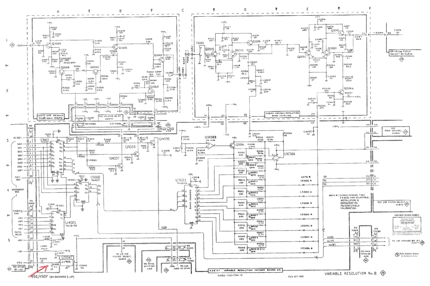


Finally, examining the front panel pcb (Variable Resolution pcb: #19) : I have found a small -5V linear regulator supplied by -15V through a 4,7 Ohm resistor and a 2uF tantale capacitor and this capacitor was presenting a nice and solid short circuit !
Once this capacitor (not easily accessible) replaced: all was correct....
Let's say: no abnormal impedances were present on different supply voltages measured on "Z axis and RF Interface (A70)" pcb.
Frankly this "after action" explanation is a "concise resume" of my troubleshooting process...
Before discovering the "solid problem, I went to a fairly radical process.
I was a little bit "desperate" and I have removed all pcb's, out of main board, in order to troubleshoot (if required) the "tubes side" of the spectrum analyser.

... Once every pcb's re-inserted in their previous locations, I have re-screwed all and plug the mains cord inside the spectrum receptacle.
Power on ..and nothing happens !!!
The screen is lighting, some trace seems to be memorized and displayed...That was all !
After one hour of intensive reflection...I have look the Led status on the CPU PCB.


With switches 8 open and switch 7 closed, CPU starts a Power Up self test.
The result is displayed (if error) on Led's located on CPU board.
In my case: some test cases were passing Ok but led "ROM" was lighted as reported error ...!
But, sometimes, test cases were passing completely...
After lot of retries, I have deeply used a contact cleaner on all CPU board 'pins, and finally:
spectrum analyser was completely working nice !
